Class meeting on Thursday the 13th of January:
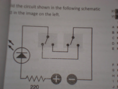
The first project was to create a double switch using a resistor, a LED and 2 switches. The schematic for achieving this is shown below.

In the schematic you can see that the LED is off in its default position, to turn it on you can close the loop by switching the left or right switch. An example of how this works is shown below.
The next project was to demonstrate the function of a relay. The schematic for this is shown below.

A relay functions as a mechanical switch which can change its condition if an electric current is applied to the electromagnet held inside of it. In the following video, the button is used to control a current which is applied to the electromagnet. One path through the relay runs to the green LED and the other path runs to the red LED. When the button is pressed, current is applied to the electromagnet and the relay switches positions, this causes the red LED to light up.
The last breadboard project for the night was to demonstrate the function of an Oscillating Relay. To get a relay to oscillate you need to run the electromagnet in parralell with a capacitor. The schematic is shown below.
 When current is applied to the electromagnet and capacitor in paralell some of the current goes into the electromagnet, and some goes into the capacitor. While the capacitor is charging, the majority of the current travels through the electromagnet. When the capacitor discharges, the current breifly ceases to travel through the electromagnet which causes the switch inside the relay to relax to its default state. The capacitor then begins to charge again, which causes current to flow through the magnet and change the switch's position. This process continues as long as there is current in the circut.
To observe the phenomenon you can watch the video below... the comentary at the end is due to the fact that all of our experiments occur late at night.
The last thing we worked on on thursday was to build the squarebot from the vex inventors guide. I made a few adjustments to the design and turned it into a dragster. 
Preliminary testing on the dragster shows that it can pop a wheelie and maintain its upright position while driving. I will try to post video of its antics on tuesday.
 In the schematic you can see that the LED is off in its default position, to turn it on you can close the loop by switching the left or right switch. An example of how this works is shown below.


No comments:
Post a Comment