Monday, January 31, 2011

Poppin Wheelies


Thursday's Class was dedicated to illustrating the benefits provided by rotation sensors, and how they improve the accuracy of open loop navigation. The above video is my attempt to navigate a maze made out of black tape using a vex robot... while popping a wheelie.
As you can see, I did not get anywhere close to the target of completing the maze. The reasons for this include the considerable slippage of the tires due to the high power levels, and the difficulty of making precise turns when the robot is in the wheelie position.

After the first attempt at the maze, we were asigned our project teams, and were set to work on using sensor data to improve the accuracy of our robot's performance. The rotation sensors allowed us to make estimates of how far the robot had traveled based on its feedback. As you can see from the following video, a more controlled path through the maze was made possible by these sensors.

(Video to be posted once converted)

Thursday, January 27, 2011

Oscilloscope intro


Wednesday's Class was dedicated to mastering the 555 relay, and observing the effects on an oscilloscope. If Properly configured the 555 relay generated a square wave pattern, which looks like this: _-_-_-_-_-_-_-_-_-_-_-_-_-_-_-_-_-_-_-_-_-_-_-_-_-_-_-_-_-_-_-_-

The rest of the class was spent demonstrating our Hack a toy projects and playing around with software.

-Brian

Wednesday, January 26, 2011

Pan/Tilt Laser platform

For the mechatronics class, I used a Pan/Tilt Platform with a laser attached to create a targeting system which is controlled by a laptop interface. The video below explains how the system works.

If you would like to duplicate my results the first thing you need to do is collect the following components:
A Tilt/Pan Platform (Hobby king has an affordable one)
http://www.hobbyking.com/hobbyking/store/uh_viewItem.asp?idProduct=11442
2 Servo Motors
a DB9 Female connector to PC
a USB to serial cable
and a prolific USB to serial driver.
Once you have the driver installed, wire your DB9 according to the following schematic.

The next step is to get a PIC 08M micro-controller and wire it to a breadboard or proto-board according to the following schematic.
Finally, you need 2 servo motors and a laser, wired according to the following schematic. The diode in the diagram is a back EMF suppression Diode, and it is necessary to protect your components when you work with electric motors. Once the circuits are completed, the next step is download the picaxe programming editor. The software can be found at (http://www.rev-ed.co.uk/picaxe/software.htm). The following code, when uploaded to the board, will cause the pic to wait for serial input on pin 4.
Once the code is uploaded, switch the serial wire (Tx) from program mode to serial input mode and open up a terminal window. The programming editor has a built in terminal screen, but if you want to directly interface with the PIC without having to repeatedly press the SEND button I recommend downloading a terminal emulator. Indigo Terminal Emulator has a 45 day free trial, and can be found at
(http://download.cnet.com/Indigo-Terminal-Emulator/3000-2085_4-10260012.html).
Once you have opened a Terminal screen, the WASD controls can be used to point the laser in any direction you want and is only limited by the range of your tilt/pan platform.

Good luck!

Monday, January 24, 2011

Serial in and out

The Major project for Jan 20 was to demonstrate communication between the picaxe in serial mode. It was mighty frustrating because I did not understand the general properties of the picaxe chip. The major hurtle was realizing that pins 2 and 6 both need to have a path to ground in order for serial communication to work. The functional layout is below:

Using the picaxe programming editor, I was able to upload the following code.

Using the Terminal emulator built into the program allows serial communication with the picaxe chip. The next step is to combine serial communication with motor control and the hack a toy project will be complete.

-B

Thursday, January 20, 2011

Microcontrolling the LED


Wednesday Jan 19:

The focus for this class was learning to interact with a pic micro-controller through a USB to serial output. In the photo below, the black 8 pin chip is the pic micro-controller of type 08M.
Part no. 12f683. The white wire at the top of the photograph is the Tx to computer wire, the grey wire on the left side of the photo is the communications FROM the computer, and it is wired in series with a resistor to prevent an overload of the communications pin.
Setting up the board was painless, but getting the serial communication to work took the bulk of the head scratching.

As it turns out, I was trying to program with an old version of the picaxe programming editor. The newest version (v5.3.2) solved my communication problems and it can be found here:
http://www.rev-ed.co.uk/picaxe/software.htm

The rest of the evening was spent trying to get this servo PAN/TILT platform to interface with the pic micro-controller.
The PIC has built in syntax for controlling servo motors;
The code I used to move the servo by changing the amount of light hitting a LDR (Light Dependent resistor) is shown below.
============================================
init: servo 2,125
main:
readadc 4, b0
serout 0, N2400, (#b0)
serout 0, N2400, (10,13)
if b0> 95 then position
if b0< 96 then outdown

goto main

position:
servopos 2, b0
pause 200
goto main

outdown:
servopos 2, 95
pause 200
goto main
=====================================

Wednesday, January 19, 2011

Logical Probing

Transistors are the electrical companion to the relay. They take the function of a switch which only activates when current is applied to the base wire. The first advanced project for the transistor is detailed in schematic below. The current applied to the base wire is variable based on the setting of the potentiometer (P1). If the resistance is high, the current to the base is low, and the transistor passes a low current. If the resistance is low, the current is high, and the transistor passes a high current.

Points A1 and A2 are measurement points for the current in the circuit. My multimeter has a broken fuse, so I was unable to measure the current in my circuit, but I was able to measure voltage changes across the potentiometer and transistor. A picture of my version of the circuit is detailed below.

The logic probe was the major project for the day. It is the first project which is intended to be a permanent addition to the electrical tool kit, and is assembled from parts which cost less than $5.
The basic model, with one LED, has a default condition of a dim LED when it is connected to power and ground. When it probes a high voltage location the light gets brighter, when it probes a ground location it turns off. The more advanced model contains 2 LEDs, and has a default condition of a dim green LED. When power is probed, the red LED lights, when ground is probed, the green LED gets brighter.


Sunday, January 16, 2011

Wiring, Relays and RC robots

Class meeting on Thursday the 13th of January:

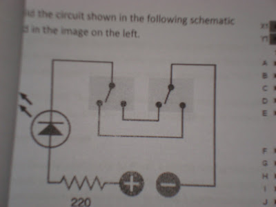
The first project was to create a double switch using a resistor, a LED and 2 switches. The schematic for achieving this is shown below.

In the schematic you can see that the LED is off in its default position, to turn it on you can close the loop by switching the left or right switch. An example of how this works is shown below.


The next project was to demonstrate the function of a relay. The schematic for this is shown below.


A relay functions as a mechanical switch which can change its condition if an electric current is applied to the electromagnet held inside of it. In the following video, the button is used to control a current which is applied to the electromagnet. One path through the relay runs to the green LED and the other path runs to the red LED. When the button is pressed, current is applied to the electromagnet and the relay switches positions, this causes the red LED to light up.


The last breadboard project for the night was to demonstrate the function of an Oscillating Relay. To get a relay to oscillate you need to run the electromagnet in parralell with a capacitor. The schematic is shown below.


When current is applied to the electromagnet and capacitor in paralell some of the current goes into the electromagnet, and some goes into the capacitor. While the capacitor is charging, the majority of the current travels through the electromagnet. When the capacitor discharges, the current breifly ceases to travel through the electromagnet which causes the switch inside the relay to relax to its default state. The capacitor then begins to charge again, which causes current to flow through the magnet and change the switch's position. This process continues as long as there is current in the circut.


To observe the phenomenon you can watch the video below... the comentary at the end is due to the fact that all of our experiments occur late at night.


The last thing we worked on on thursday was to build the squarebot from the vex inventors guide. I made a few adjustments to the design and turned it into a dragster.


Preliminary testing on the dragster shows that it can pop a wheelie and maintain its upright position while driving. I will try to post video of its antics on tuesday.

Wednesday, January 12, 2011

The breaking of the bread(board)


Today we had the breaking in of the breadboards:
behold the glory of 3 Light emitting diodes wired in parallel.

The green one is emitting a small amount of light because it has 2 large resistors regulating is current, (approximately 10400 ohms) the middle LED has a 100 ohm resistor and the top LED is wired to a 1000 ohm resistor. As you can see, the greater the resistance, the less light emitted from the diode.

Today we were introduced to the wonders of the multimeter. We used it to check for continuity in our soldered circuits from day one, we used it to make sure that our 5 volt power supplies were not going to explode when we put them into the wall, and we used it to check voltage and resistance in a circuit built on a breadboard.

Resistors are color coded to display their resistance, and each color represents a decimal value or a power of 10.
The following image explains how this works:
Finally, we were assigned our vex robotics kits today, which we will be using to create a square bot and to build the final project.

Tune in tomorrow, same bat time, same bat channel!

Tuesday, January 11, 2011

January 11 2011 - first class meeting


Summary of activities:

Today's class covered basic soldering techniques, some of which include:

The use of flux
determining the difference between good and bad solder jobs
how not to get injured

To test these theories we attached components haphazardly to a board thusly:

Additionally, we butchered a 5 volt power supply and soldered wires to the positive and negative ends. Then we applied heat shrink to protect the soldered connections.

This tangled mess was the result:
The important part is that the wires on the left end of the picture can be used to power a breadboard! Happy melting, and see you all Wednesday.